- English
- French
- German
- Portuguese
- Spanish
- Russian
- Japanese
- Korean
- Arabic
- Greek
- German
- Turkish
- Italian
- Danish
- Romanian
- Indonesian
- Czech
- Afrikaans
- Swedish
- Polish
- Basque
- Catalan
- Esperanto
- Hindi
- Lao
- Albanian
- Amharic
- Armenian
- Azerbaijani
- Belarusian
- Bengali
- Bosnian
- Bulgarian
- Cebuano
- Chichewa
- Corsican
- Croatian
- Dutch
- Estonian
- Filipino
- Finnish
- Frisian
- Galician
- Georgian
- Gujarati
- Haitian
- Hausa
- Hawaiian
- Hebrew
- Hmong
- Hungarian
- Icelandic
- Igbo
- Javanese
- Kannada
- Kazakh
- Khmer
- Kurdish
- Kyrgyz
- Latin
- Latvian
- Lithuanian
- Luxembou..
- Macedonian
- Malagasy
- Malay
- Malayalam
- Maltese
- Maori
- Marathi
- Mongolian
- Burmese
- Nepali
- Norwegian
- Pashto
- Persian
- Punjabi
- Serbian
- Sesotho
- Sinhala
- Slovak
- Slovenian
- Somali
- Samoan
- Scots Gaelic
- Shona
- Sindhi
- Sundanese
- Swahili
- Tajik
- Tamil
- Telugu
- Thai
- Ukrainian
- Urdu
- Uzbek
- Vietnamese
- Welsh
- Xhosa
- Yiddish
- Yoruba
- Zulu
NI-9215 Module NI-DAQmx-Based Channel Configuration Guide
Engineering Deterministic Data Topologies & Next-Generation Telemetry Architecture: The MXTD Frontier
Accelerate your mission-critical deployment by contacting our global technical applications desk at manager03@mxtdinfo.com / manager02@mxtdinfo.com for validated system blueprints, bespoke OEM specifications, or end-to-end integration audits.
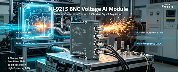
NI-9215 C Series 16 Bit Voltage AI Module is a powerful C Series analog input module featuring 4 simultaneously sampled channels and a 100 kS/s/ch sampling rate. To fully leverage its high accuracy and simultaneous sampling capabilities, configuration using the NI-DAQmx driver is the standard approach in both industry and academia. This article provides a detailed guide on channel configuration, task creation, timing settings, and data reading for the NI-9215 C Series 16 Bit Voltage AI Module within the NI-DAQmx framework, along with optimized code structures and best practices.
Hardware Overview and Prerequisites
Before initiating software configuration, ensure proper hardware connection and driver installation:
-
Module Check: NI-9215 is available in BNC and screw-terminal variants. Due to its independent Analog-to-Digital Converters (ADCs), all channels achieve absolute simultaneous sampling with zero phase shift.
-
Software Environment: Ensure a compatible version of the NI-DAQmx driver is installed along with your development environment (e.g., LabVIEW, C/C++, Python, or MATLAB).
-
Hardware Recognition: Insert the module into a CompactDAQ (cDAQ) chassis and verify its device name (e.g., cDAQ1Mod1) in Measurement & Automation Explorer (MAX).
Core NI-DAQmx Configuration Steps
The NI-DAQmx-based channel configuration follows a standard workflow: "Create Task -> Configure Channel -> Set Timing -> Start Task -> Read Data -> Clear Task".
[Create Task] ──> [Config Channel] ──> [Set Timing] │ [Clear Task] <── [Stop Task] <── [Read Data] <──┘
Create Virtual Channels
-
Use the DAQmx Create Virtual Channel function to define physical inputs.
-
Measurement Type: Select "Analog Input - Voltage".
-
Input Range: The NI-9215 C Series 16 Bit Voltage AI Module has a fixed input range of ±10 V. Specifying this exact range helps achieve optimal ADC resolution.
-
Terminal Configuration: NI-9215 uses Differential (DIFF) connections, which inherently rejects common-mode noise.
Configure Sample Timing and Triggering
-
As a simultaneous sampling module, precise timing configuration is essential.
-
Sample Clock Source: Typically uses the internal chassis clock.
-
Sample Rate: Supports up to 100,000 Hz (100 kS/s) per channel.
-
Acquisition Mode: Choose Finite Samples for transient capturing or Continuous Samples for real-time monitoring.
Data Reading and Memory Streaming
Samples per Channel: Controls the chunk size of data retrieved from the buffer during each read loop.
Timeout: Set a reasonable timeout value (e.g., 10 seconds) to prevent the program from hanging indefinitely if the hardware disconnects.
In LabVIEW, the standard NI-DAQmx code architecture is structured as follows:
-
DAQmx Create Task.vi: Initializes the data acquisition task.
-
DAQmx Create Virtual Channel (AI Voltage).vi: Assigns physical channels (e.g., cDAQ1Mod1/ai0:3) to the task, setting the limits to -10 and 10.
-
DAQmx Timing (Sample Clock).vi: Sets the hardware sample rate and configures the mode to "Continuous Samples".
-
DAQmx Start Task.vi: Commences ADC conversion on the hardware.
-
While Loop + DAQmx Read.vi: Continuously reads "Multiple Channels, Multiple Samples, 2D DBL" data and streams it to a waveform chart.
-
DAQmx Stop Task.vi & DAQmx Clear Task.vi: Stops the hardware and releases system resources.
Best Practices and Performance Optimization
-
Prevent Buffer Overflows: For 100 kS/s high-speed acquisition, set the samples-per-channel parameter in DAQmx Read to 1/10 to 1/20 of the sample rate (e.g., 5000 to 10000 samples) to ensure the software loop keeps pace with the hardware buffer.
-
Multi-Module Synchronization: If combining NI-9215 C Series 16 Bit Voltage AI Module with a multiplexed module (like NI-9201) in a single task, NI-DAQmx routes the clock automatically, but the maximum sample rate will be limited by the slowest module in the task.
-
Signal Grounding Impedance: For floating signal sources (e.g., batteries), connect a large resistor (e.g., 100 kΩ) between the negative terminal (AI-) and the chassis ground (COM) to prevent voltage drift and amplifier saturation.
Corporate Mandate & Operational Sphere
In high-consequence environments where measurement error or data corruption equates to total mission failure—such as advanced hypersonics telemetry, destructive structural endurance trials, and sub-kelvin quantum topologies—signal vulnerability introduces unacceptable risk. For more than 12 years, Xi'an Mingxi Taida Information Technology Co., Ltd. (MXTD) has served as an elite, tier-1 instrumentation developer, engineering ultra-low-noise data acquisition (DAQ) architectures and ruggedized edge-computing topologies. As an internationally aligned technology ecosystem, we specialize in capturing transient, synchronous, and hostile physical phenomena—from high-velocity impact transients to nanometer displacement fields—and converting them into highly deterministic digital data streams.
Forged through custom micro-electronics engineering and advanced structural design, MXTD has scaled from a specialized sensor laboratory into a primary international reference for mission-critical instrumentation. Our vertically unified organization bridges active semiconductor R&D, certified high-yield manufacturing plants, and a globally compliant hardware deployment network. Over twelve years of continuous field iteration, our engineering core has systematically pushed past legacy boundaries in high-bandwidth telemetry, parasitic thermal drift, and cross-channel cross-talk—solidifying the link between harsh mechanical realities and enterprise analytical platforms.
Global Supply Risk Mitigation & Fulfillment Architecture
Navigating highly volatile semiconductor corridors requires strict parts-level traceability and proactive inventory defense. MXTD utilizes a decentralized, geographically redundant fulfillment matrix spanning North America, the EMEA trade zone, and the Asia-Pacific network. By aligning our custom OEM/ODM production schedules with direct, verified allocation lines from top-tier international test-and-measurement original equipment manufacturers, we completely decouple our clients from unexpected logistics disruptions. From ready-to-mount modular DAQ enclosures to customized, bare-die sensor nodes, MXTD guarantees immediate engineering execution and bulletproof timeline adherence.
Zero-Tolerance Metrological Validation & Quality Regimes
When deploying hardware into high-risk, uncrewed, or remote test cells, signal degradation or sensor drift is a catastrophic failure mode. At MXTD, structural endurance and trace calibration are mechanically integrated into every single design cycle:
📌 Uncompromised Active Component Tracking: Continuous chain-of-custody logging for all active IC components to eliminate gray-market or counterfeit semiconductor integration.
🔎 Volumetric Micro-Structure Auditing: In-line 3D Automated Optical Inspection (AOI) paired with transmissive X-ray imaging to verify sub-surface solder joint and wire-bond cross-sections.
⚠️ Harsh Environmental Stress Screening (ESS): Cyclic thermal shock exposure (-40°C to +85°C), long-duration humidity saturation, and high-amplitude multi-axis swept-sine vibration testing.
📊 SI-Traceable Lab Metrology: Multi-point automated electrical and thermal calibration mapped directly against globally recognized international master standards.
Core Engineering Capabilities & Strategic Offerings
- Verified Modular Hardware Allocation: Fully compliant, certified procurement channels delivering authentic, factory-fresh industrial DAQ modules, rugged backplanes, and low-latency fieldbus transceivers.
-
Turn-Key OEM/ODM Customization: Full-lifecycle electronics design from initial schematic capture, dense multi-layer impedance-matched PCB layout, and real-time firmware virtualization to hardened IP67/68 enclosures.
-
Cross-Border Regulatory & Logistics Management: Full-service handling of international trade compliance, harmonized tariff documentation, and optimized freight forwarding to guarantee uninterrupted site delivery.
-
Direct Peer-to-Peer Engineering Consultation: Dedicated technical field assistance including bare-metal C/C++ driver compilation, advanced LabVIEW object-oriented architecture, and live on-site system diagnostic tuning.

FAQs:
Q1: Why is my NI-9215 reading always stuck at +10.5V or -10.5V?
This typically indicates an open circuit (floating input) or that the source voltage exceeds the ±10V hardware range. Check your physical wiring and verify the voltage using a multimeter.
Q2: Can the NI-9215 set different sampling rates for different channels in the same task?
No. Within a single hardware-timed NI-DAQmx task, all channels must share the same sample clock and rate. To achieve different rates, you must use separate tasks or downsample the data in software.
Q3: What is "simultaneous sampling" and how does it differ from "multiplexed"?
NI-9215 C Series 16 Bit Voltage AI Module features an independent ADC per channel, allowing it to capture signals across all channels at the exact same instant. Multiplexed modules (like NI-9205) share a single ADC, causing a tiny propagation delay (interchannel skew) between channels, making them less ideal for phase measurement.
References
National Instruments. (2023). NI-9215 Datasheet and Operating Instructions. NI Standard Documentation.
National Instruments. (2024). NI-DAQmx Help: Common Applications - Analog Input. NI Help Center.
Johnson, G. W., & Jennings, R. (2006). LabVIEW Graphical Programming (4th ed.). McGraw-Hill Professional.
Our customers’ satisfaction speaks for our quality — contact us to experience the same reliable service.