- English
- French
- German
- Portuguese
- Spanish
- Russian
- Japanese
- Korean
- Arabic
- Greek
- German
- Turkish
- Italian
- Danish
- Romanian
- Indonesian
- Czech
- Afrikaans
- Swedish
- Polish
- Basque
- Catalan
- Esperanto
- Hindi
- Lao
- Albanian
- Amharic
- Armenian
- Azerbaijani
- Belarusian
- Bengali
- Bosnian
- Bulgarian
- Cebuano
- Chichewa
- Corsican
- Croatian
- Dutch
- Estonian
- Filipino
- Finnish
- Frisian
- Galician
- Georgian
- Gujarati
- Haitian
- Hausa
- Hawaiian
- Hebrew
- Hmong
- Hungarian
- Icelandic
- Igbo
- Javanese
- Kannada
- Kazakh
- Khmer
- Kurdish
- Kyrgyz
- Latin
- Latvian
- Lithuanian
- Luxembou..
- Macedonian
- Malagasy
- Malay
- Malayalam
- Maltese
- Maori
- Marathi
- Mongolian
- Burmese
- Nepali
- Norwegian
- Pashto
- Persian
- Punjabi
- Serbian
- Sesotho
- Sinhala
- Slovak
- Slovenian
- Somali
- Samoan
- Scots Gaelic
- Shona
- Sindhi
- Sundanese
- Swahili
- Tajik
- Tamil
- Telugu
- Thai
- Ukrainian
- Urdu
- Uzbek
- Vietnamese
- Welsh
- Xhosa
- Yiddish
- Yoruba
- Zulu
PIL 50-110 Series PCI Relay Board SPDT
2. 100% thermal cycling stress testing: Each relay undergoes three cycles between -20°C and +85°C to eliminate early failures
This PIL 50-110 series offers two contact configurations: SPDT (Single-Pole Double-Throw/Changeover) and SPST (Single-Pole Single-Throw/Normally Open).
The PIL 50-110 Series PCI Relay Board SPDT is the latest generation of PCI general-purpose reed relay switching cards introduced by Pickering Interfaces, and is part of the 50-110B/50-115B product family.This series offers two contact configurations: SPDT (Single-Pole Double-Throw/Change over) and SPST (Single-Pole Single-Throw/Normally Open). Each card can accommodate 32 or 64 relay channels, with signal input via a 200-pin female LFH connector on the front panel.
The PIL 50-110 series is a mature product that has evolved over time on Pickering’s PCI platform, having undergone three generations of iteration: 50-110 → 50-110A → 50-110B. While maintaining core electrical performance, each generation has featured continuous upgrades in firmware compatibility, diagnostic tool support, warranty coverage, and operating system support.
MXTD Wholesaler
For more than a decade, Xi'an Mingxi Taida Information Technology Co., Ltd. (MXTD) has been a trusted technology leader, engineering innovative solutions that fuel enterprise growth. By seamlessly merging high-level product development, international logistics, and localized technical support, we offer an agile business model that addresses every stage of your operational needs. Our strong foundation in advanced research and precision manufacturing allows us to design and build durable tech portfolios capable of performing in the most demanding industrial environments.
Our specialized capabilities and market advantages include:
- Strategic Global Footprint: We operate a vast international distribution network that reliably services key markets across North America, South America, Europe, and Africa.
- Unified Procurement Solutions: We consolidate your supply chain by pairing our own proprietary hardware innovations with premium authorized distribution of world-class multinational tech brands.
- Uncompromising Quality Assurance: Every component and system we deliver is subjected to rigorous benchmarking, comprehensive testing, and meticulous quality control protocols.
The Key Characteristic- PIL 50-110 Series PCI Relay Board SPDT
| Instrument-Grade Ruthenium Contact Reed Relays | Features high-quality sputtered ruthenium electrical contact reed relays manufactured in-house by Pickering Electronics (a sister company), optimized specifically for switching low-level signals and offering excellent contact resistance stability |
| High Reliability | Relay life exceeds 10⁸ operations (low-power load) and exceeds 10⁶ operations at full power load |
| Fast Switching Speed | Typical operation time: 250 µs (including bounce); release time: 250 µs (typical) |
| Wide range and flexible configuration | Available in SPDT (32/64-channel) and SPST (32/64-channel) configurations to meet both switching and normally open switching requirements |
| eBIRST™ Diagnostic Support | A diagnostic testing tool for Pickering’s eBIRST switching system that automatically detects faults such as relay soldering defects, open circuits, and high contact resistance, thereby minimizing downtime. |
| BIRST Built-in Self-Test | Built-in relay self-diagnostic function allows faulty relays to be identified without the need for external devices or special skills. |
| Complete Software Driver Stack | Provides three levels of drivers—VISA, IVI, and kernel-level (Direct I/O)—and supports Windows and Linux operating systems. It is compatible with mainstream development environments such as LabVIEW, LabWindows/CVI, Visual Studio, and MATLAB. |
| CE Compliance Certification | Fully compliant with EU directives: Low-Voltage Safety EN 61010-1:2010, EMC Immunity EN 61326-1:2013, and EMC Emissions EN 55011:2009+A1:2010 |
| PCI 2.0 Compliant | Fully compatible with PCI Specification 2.0,32-bit +5V 信号环境32-bit +5V Signal Environment |
| On-board backup relay | Spare reed relay slots are reserved on the PCB to facilitate quick on-site maintenance and replacement, minimizing downtime. |
| SoftCenter™ Technology | Pickering’s patented soft-packaging technology provides maximum cushioning and protection for fragile glass reed switches, extending their service life. |
| Magnetic Shielding | The internal Mu-metal magnetic shielding design allows for high-density side-by-side installation without causing magnetic interference issues. |
Pickering’s general-purpose reed relay cards for PCI platforms have evolved through three generations.
| Generation | Model | eBIRST Support | Position |
| First Generation | 50-110/115/120/125 | Partial support | Basic Edition |
| Second Generation | 50-110A/115A | Full support | Upgraded Version |
| Third Generation | 50-110B/115B | Full support | Main version |
The 50-110B series is positioned as the flagship product line for general-purpose reed relay switching on the Pickering PCI platform, complementing the following products:
- 50-120B/125B (shielded versions): Add electromagnetic shielding to the 50-110B design, suitable for applications with higher bandwidth and crosstalk performance requirements.
- 50-131A/50-132 (2A Relay Cards): Based on electromechanical relays, these are suitable for medium-power (2A/60W) switching applications.
- 50-510A/511A/512A/513A (Matrix Cards): Featuring dedicated matrix topologies (22×4, 44×4, etc.), these are suitable for large-scale crosspoint switching.
Switch Topology Funtions- PIL 50-110 Series
| Model | Number of Relays | Contact | Default State |
| 50-110B-021 | 32 | SPDT(Form C / Conversion Type) | Terminal C is connected to Terminal B (normally closed circuit) |
| 50-110B-121 | 64 | SPDT(Form C / Conversion Type) | Terminal C is connected to Terminal B (normally closed circuit) |
| 50-115B-021 | 32 | SPST(Form A / Normally Open) | Open Circuit (C-A is conductive after the relay is energized) |
| 50-115B-121 | 64 | SPST(Form A / Normally Open) | Open Circuit (C-A is conductive after the relay is energized) |
Signal Routing Functionality
- SPDT Model (50-110B): Each channel includes a common terminal (C) and two output terminals (A/B). In the default state, the C-B path is closed (normally closed); when the relay is energized, it switches to the C-A path being closed (normally open). Supports switching between two signal paths.
- SPST Model (50-115B): Each channel includes a common terminal (C) and one output terminal (A). In the default state, the circuit is open; when the relay is energized, the C-A path becomes conductive. Suitable for building simple signal switching matrices.
Programming Control
- All relays are centrally managed by a single sub-unit
- SPDT/SPST models: Controlled via bits; each bit corresponds to one relay
- Supports single-channel operation (OpBit) and batch mode operation (WriteSub/setChannelPattern)
- The Relay Lookup Table maps logical channel numbers to the physical relay locations on the PCB, facilitating fault diagnosis
Diagnostics and Maintenance
- eBIRST Diagnostics: Connect the eBIRST tool via the USB port to automatically scan all relay paths and detect abnormalities such as soldering defects, open circuits, and contact resistance issues.
- BIRST Built-in Self-Test: Built into matrix-type products, allowing diagnostics to be run without external devices.
- Test Panels Graphical Interface: After installing the driver, you can intuitively operate all relays through the graphical panel.
- PILMon Command-Line Tool: Provides a complete command-line interface; enter “HE” to view help.
- Diagnostic Report Tool: Generates PCI configuration diagnostic reports to assist in troubleshooting installation issues.
Switch Specifications of the PIL 50-110 Series PCI Relay Board SPDT
| Parameters | 50-110B(SPDT) | 50-115B(SPST) |
| Switch Type | Ruthenium Reed | Ruthenium Reed |
| Maximum Switching Voltage | 150 VDC / 100 VAC* | 150 VDC / 100 VAC* |
| Maximum Power | 3 W | 20 W |
| Maximum Switching Current | 0.25 A | 1 A |
| Maximum Current Rating | 1.25 A | 1.25 A |
| On-resistance | <800 mΩ(Typical 400 mΩ) | <800 mΩ(Typical 400 mΩ) |
| Open-Circuit Resistance | >10⁹ Ω | >10⁹ Ω |
| Crosstalk (100 Ω balanced) | 80 dB (1 MHz), 72 dB (10 MHz), 62 dB (25 MHz) | 80 dB (1 MHz), 72 dB (10 MHz), 62 dB (25 MHz) |
| Isolation (100 Ω balanced) | 75 dB (1 MHz), 60 dB (10 MHz), 55 dB (25 MHz) | 75 dB (1 MHz), 60 dB (10 MHz), 55 dB (25 MHz) |
| Operation Time | <0.5 ms, Typical 0.25 ms | <0.5 ms, Typical 0.25 ms |
| Release Time | <0.5 ms, Typical 0.25 ms | <0.5 ms, Typical 0.25 ms |
| Expected Service Life (Low Power) | >1×10⁸ / time | >1×10⁸ / time |
| Expected Service Life (at Full Power) | >1×10⁶ / time | >1×10⁶ / time |
Physical Specifications- PIL 50-110 Series
| Board Form Factors |
Single-bay, short length PCI(Single slot short PCI format) |
| Signal Interface | 200-pin female LFH connector |
| Signal Environment |
+5V only |
| PCI Compliance | PCI Specification 2.0, 33 MHz, 32-bit |
Environment
| Parameters | Working Conditions | Storage/Shipping Conditions |
| Temperature | 0°C to +55°C | -20°C to +75°C |
| Humidity | ≤90% Non-condensing | ≤90% Non-condensing |
| Elevation | 5000 m | 15000 m |
Security and Compliance
| Standards | Applicable Directives |
| Low-Voltage Safety | EN61010-1:2010 |
| EMC Immunity | EN61326-1:2013 |
| Launch | EN55011:2009+A1:2010 |
| Quality Management System | ISO 9001(Reg No. FM38792) |
Part of the PIL 50-110 Series
| Model | Description | Number of relays | Contact Configuration | Platform |
| 50-110B-021 | PCI Reed Relay Card | 32 | SPDT Conversion Type | PCI |
| 50-110B-121 | PCI Reed Relay Card | 64 | SPDT Conversion Type | PCI |
| 50-115B-021 | PCI Reed Relay Card | 32 | SPST Normally Open | PCI |
| 50-115B-121 | PCI Reed Relay Card | 64 | SPST Normally Open | PCI |
Electrical Specifications
| Items | 50-110B(SPDT) | 50-115B(SPST) | Test Conditions |
| Maximum Switching Voltage (DC) | 150 V | 150 V | The signal source must be isolated from the mains power supply |
| Maximum Switching Voltage (AC) | 100 V | 100 V | The signal source must be isolated from the mains power supply |
| Maximum Power | 3 W | 20 W | Resistive Load |
| Maximum Switching Current | 0.25 A | 1 A | / |
| Maximum Current Rating | 1.25 A | 1.25 A | Consecutive |
| Initial On-Resistance | <800 mΩ | <800 mΩ | Typical values 400 mΩ |
| Initial Disconnection Resistance | >10⁹ Ω | >10⁹ Ω | / |
| Differential Thermal Drift | <20 µV | <30 µV | / |
| Crosstalk @ 1 MHz | 80 dB | 80 dB | 100Ω Load Balancing |
| Crosstalk @ 10 MHz | 72 dB | 72 dB | 100Ω Load Balancing |
| Crosstalk @ 25 MHz | 62 dB | 62 dB | 100Ω Load Balancing |
| Isolation @ 1 MHz | 75 dB | 75 dB | 100Ω Load Balancing |
| Isolation @ 10 MHz | 60 dB | 60 dB | 100Ω Load Balancing |
| Isolation @ 25 MHz | 55 dB | 55 dB | 100Ω Load Balancing |
| Operation Time (including bounce) | <0.5 ms (Typical 0.25 ms) | <0.5 ms (Typical 0.25 ms) | / |
| Release Time | <0.5 ms (Typical 0.25 ms) | <0.5 ms (Typical 0.25 ms) | / |
Installation Precautions
- The card contains electrostatic-sensitive components; before handling, discharge static electricity by touching the antistatic bag to a metal part of the chassis.
- Perform installation with the system powered off but still grounded.
- The host chassis must be properly connected to the utility power supply and the facility’s safety ground.
- Do not use in safety-critical circuits.
- Do not use for utility power circuit switching.
- The signal source and the device under test must be completely isolated from the utility power supply.
Customization Services
We recognize that standard, off-the-shelf equipment often falls short of the rigorous demands of highly specialized technical operations. To address these unique challenges, our veteran engineering department offers full-scale, built-to-order OEM and ODM customization services designed around your exact operational parameters. From adjusting complex frequency spectrums and developing niche triggering mechanisms to engineering custom structural enclosures, we maintain a transparent, collaborative design process to turn your concept into the perfect high-performance reality.
Our custom engineering framework ensures:
- Precise Technical Alignment: Every modification is engineered to match your specific environmental, electrical, or structural requirements.
- Agile and Adaptive Design: Our flexible development workflow adapts to your project goals, speeding up time-to-market while staying aligned with your evolving needs.
- Uncompromising Quality Controls: We implement the same rigorous testing protocols for custom designs as we do for our mainline products, ensuring peak reliability.
By combining flexible engineering with strict benchmarking, we deliver specialized equipment that integrates seamlessly into your workflow without ever sacrificing safety or performance.

Using:
- Building compact switching networks in ATE systems
- Scaling signal routing and data acquisition systems
- Driving external devices (such as indicator lights, solenoid valves, etc.)
- Managing low-level/cold-switch signal paths
- Multi-channel signal distribution in functional testing
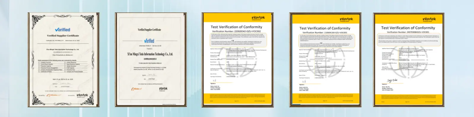

FAQs:
Q: In Windows Device Manager, the card is displayed as 'PCI Device' with a yellow exclamation mark, or as 'Pickering Switch Card' but cannot be controlled. What should I do?
A:
If it displays 'PCI Device' with an exclamation mark, it means the driver is not correctly bound. You can right-click and update the driver in Device Manager, select 'Manually Specify Path' and point it to the installed Pickering official driver.
If it displays 'Pickering Switch Card', it means the currently installed .inf driver file version is lower than the production batch of the hardware and cannot achieve software mapping. It is recommended to uninstall the existing Pickering driver software and download the latest version from the official website for installation.
Q: How can I resolve the issue of not being able to find the board in NI MAX (Measurement & Automation Explorer) software or being unable to access it via NI-VISA?
A:
Pickering boards support two low-level driver modes: Direct I/O and VISA driver.
If you need to control via NI-VISA or LabVIEW, you must ensure that you download and install the Pickering Pipx40 NI-VISA driver.
In NI MAX, go to Tools -> NI-VISA -> VISA Options, then to General Settings, and check "Show all devices accessible to VISA". After rescanning, it will be correctly mounted to the NI automation system.
Q: How much voltage and current can the 50-110 series boards switch? Can it be connected to 220V mains power?
A:
Do not connect directly to mains power.
The maximum rated switching voltage for the 50-110 (and 50-110A) is 150 VDC / 100 VAC, the maximum switching power is 3W or 20W (depending on the specific sub-model), and the maximum switching current is generally between 0.25A and 1.25A.
The official specifications clearly state that to achieve the full rated operating voltage, the test signal source must be completely isolated from the mains supply and safety earth. Directly introducing mains power or a large inductive load will generate a high-voltage transient arc, instantly breaking down and melting the reed contacts.

Contact Us
Ready to integrate reliable Relay Board control into your system? Our team is here to help you select the right configuration and provide ongoing support.
Contact our technical specialists at manager03@mxtdinfo.com / manager02@mxtdinfo.com for detailed specifications, pricing information, or to discuss your custom requirements. We're committed to delivering the perfect PIL 50-110 Series PCI Relay Board SPDT solution for your application needs.
Our customers’ satisfaction speaks for our quality — contact us to experience the same reliable service.
Our customers’ satisfaction speaks for our quality — contact us to experience the same reliable service.