- English
- French
- German
- Portuguese
- Spanish
- Russian
- Japanese
- Korean
- Arabic
- Greek
- German
- Turkish
- Italian
- Danish
- Romanian
- Indonesian
- Czech
- Afrikaans
- Swedish
- Polish
- Basque
- Catalan
- Esperanto
- Hindi
- Lao
- Albanian
- Amharic
- Armenian
- Azerbaijani
- Belarusian
- Bengali
- Bosnian
- Bulgarian
- Cebuano
- Chichewa
- Corsican
- Croatian
- Dutch
- Estonian
- Filipino
- Finnish
- Frisian
- Galician
- Georgian
- Gujarati
- Haitian
- Hausa
- Hawaiian
- Hebrew
- Hmong
- Hungarian
- Icelandic
- Igbo
- Javanese
- Kannada
- Kazakh
- Khmer
- Kurdish
- Kyrgyz
- Latin
- Latvian
- Lithuanian
- Luxembou..
- Macedonian
- Malagasy
- Malay
- Malayalam
- Maltese
- Maori
- Marathi
- Mongolian
- Burmese
- Nepali
- Norwegian
- Pashto
- Persian
- Punjabi
- Serbian
- Sesotho
- Sinhala
- Slovak
- Slovenian
- Somali
- Samoan
- Scots Gaelic
- Shona
- Sindhi
- Sundanese
- Swahili
- Tajik
- Tamil
- Telugu
- Thai
- Ukrainian
- Urdu
- Uzbek
- Vietnamese
- Welsh
- Xhosa
- Yiddish
- Yoruba
- Zulu
UT526 Low Insulation Resistance Tester
2. High-precision display with 10,000 counts
3. IEC 61010 Safety Protection System
4. Reference Price: $187-$214
The UT526 is a multifunctional electrical installation tester launched by UNI-T, belonging to the grounding resistance tester product line within the electrical safety testing tools.
UT526 Low Insulation Resistance Tester product employs a large-scale integrated design combining analog circuitry, digital circuitry, and a microprocessor chip, integrating four core functions—insulation resistance testing, RCD (residual current device) testing, low resistance continuity testing, and AC/DC voltage measurement—into a single handheld instrument, providing a one-stop testing solution for electrical installation, maintenance, and inspection work.
The UT526 belongs to the UNI-T UT500 series of electrical safety test instruments, forming an entry-level multi-functional electrical tester product line together with the UT525. Within UNI-T's overall product portfolio, the UT526 Low Insulation Resistance Tester is positioned in the electrical safety testing tools category, serving the electrical safety testing needs of power system maintenance, building electrical systems, and industrial manufacturing. This product has obtained CE and UKCA certifications, strictly adheres to the IEC61010 safety standard, has an overvoltage rating of CAT III 600V, and a pollution level of Class II, making it widely applicable to various industrial and civil electrical environments.
The Core Values of The UT526
The core value of the UT526 Low Insulation Resistance Tester lies in its "multi-functionality, safety and reliability, and ease of operation." Traditional electrical safety testing often requires multiple devices such as insulation resistance testers, RCD testers, and grounding resistance testers. The UT526, however, integrates four core testing functions into one unit, significantly reducing procurement costs and on-site carrying burden. Its high-precision LCD display with 10,000 counts, red warning light, and automatic voltage release design ensure safe operation while providing stable and reliable measurement results.
The UT526 is an upgraded version of the UT525 in the same series. Both products share the same appearance design and operating logic, but there are significant differences in performance specifications. The following is a detailed comparison:
|
Comparison Dimensions |
UT525 |
UT526 |
|
Insulation resistance test voltage |
100V / 250V / 500V |
250V / 500V / 1000V |
|
Maximum range of insulation resistance |
200MΩ |
500MΩ |
|
Insulation resistance accuracy |
0.05MΩ-200MΩ: ±(5%+5) |
0.05MΩ-500MΩ: ±(5%+5) |
|
Low resistance continuous range |
0.01Ω-200Ω |
0.01Ω-2000Ω |
|
Low resistance test current |
>200mA (0.00Ω-2.00Ω) |
>200mA (0.00Ω-2.00Ω) |
|
Low resistance accuracy |
0.01Ω-200Ω: ±(2%+5) |
0.01Ω-200Ω: ±(2%+5)<br>201Ω-2000Ω: ±(5%+5) |
|
RCD test |
10/30/100/300mA |
10/30/100/300mA |
|
Voltage measurement |
0-440V AC/DC |
0-440V AC/DC |
|
Target users |
Basic electrical engineering and home improvement applications |
Professional electrician, industrial operation and maintenance, project acceptance |
UT526 Low Insulation Resistance Tester is applicable to electrical safety testing in the following areas:
-
Power distribution system testing: Insulation performance and leakage current protection testing of low-voltage distribution panels, distribution boxes, and switchgear.
-
Lightning protection system testing: Continuity and conductivity testing of lightning protection grounding devices.
-
Wiring system acceptance testing: Insulation resistance, grounding continuity, and RCD function verification of new or renovated electrical wiring projects.
-
Equipment maintenance and inspection: Periodic insulation testing of equipment such as motors, transformers, and electrical control cabinets.
-
Routine electrician inspections: A multi-functional testing tool carried by electrical maintenance personnel.
Why Choose MXTD as Your Trusted Partner?
- Over a Decade of Industry Leadership: Leverage our 12+ year proven trajectory of pioneering breakthroughs in specialized metrology and automated control architecture.
- Elite Research & Development: Benefit from cutting-edge hardware engineering that continuously pushes technological boundaries to future-proof your systems.
- Zero-Tolerance Quality Control: Minimize field operational risks through our strict validation protocols and extreme environmental stress-testing.
- Full-Lifecycle Technical Consultation: Access uninterrupted, end-to-end engineering assistance and expert intervention at every phase of your project.
- Insured Global Supply Chain: Enjoy absolute peace of mind with our secure, highly traceable international logistics networks and door-to-door freight security.
- Client-First Synergistic Alignment: Experience flexible, collaborative problem-solving tailored to match your specific long-term commercial goals.
The UT526 Low Insulation Resistance Tester adopts UNI-T's mature digital measurement technology architecture and has several core technological highlights:
-
Integrated Measurement Platform: The entire system adopts a combination design of large-scale integrated analog circuits, digital circuits, and microcomputer chips, integrating four major functional modules—insulation resistance, RCD, low resistance continuity, and voltage measurement—onto a single control platform. This ensures the consistency of measurement accuracy across all functional modules and the stability of the system.
-
High-precision display with 10,000 counts: Equipped with a large 71mm × 34mm LCD screen, it can display a maximum count of 10,000 characters, providing sufficient resolution to meet the accuracy requirements of electrical safety testing. The display interface simultaneously shows function symbols and electrical unit symbols, allowing users to intuitively read measurement results.
-
IEC 61010 Safety Protection System: Designed and manufactured in strict accordance with the IEC 61010 safety standard, and certified for CAT III 600V overvoltage level and pollution degree II. The products feature double or reinforced insulation, coupled with automatic voltage release function, ensuring operator safety from a hardware design perspective.
Compared to similar single-function testers, the UT526 Low Insulation Resistance Tester has the following differentiated advantages:
-
Four major functions are integrated: insulation resistance testing (up to 1000V), RCD leakage current protection testing, low resistance continuity testing, and AC/DC voltage measurement are all combined into one unit. Users can complete all core testing items for electrical installation acceptance without carrying multiple instruments. This integrated design not only reduces equipment procurement costs but also reduces the time wasted on changing instruments during on-site testing.
-
RCD phase switching function: Supports RCD testing with 0° and 180° phase switching, simulating the operating characteristics of residual current devices (RCDs) at different phase angles, meeting more comprehensive RCD performance testing needs. Test current covers four ranges: 10mA/30mA/100mA/300mA, suitable for testing RCDs with different sensitivity levels.
-
Automatic Voltage Release and Safety Warning: The built-in automatic voltage release function automatically releases residual charge in the tested circuit after testing, avoiding the risk of electric shock caused by capacitor energy storage. It also features a red warning light, providing a clear visual warning during high-voltage output, further enhancing operational safety.
-
TEST Single-Button Operation: Featuring a single-button operation design, users can quickly start the measurement by pressing the TEST button after selecting the measurement range. The operation process is simple and efficient. Combined with the grounding resistance zeroing function (ZERO button), the influence of test lead resistance on the measurement results can be eliminated, improving the accuracy of low-resistance measurements.
The UT526 Low Insulation Resistance Tester belongs to the grounding resistance tester series under the electrical safety testing tools category. UNI-T's electrical safety testing tool line covers multiple sub-series including insulation resistance testers, grounding resistance testers, clamp-on grounding resistance testers, and comprehensive electrical testers, covering complete user needs from entry-level to professional-level.
Specifically, the UT526's positioning can be summarized as follows:
-
Entry-level multi-functional electrical tester: Targeting electricians, electrical maintenance personnel, and small engineering contractors, the UT526 Low Insulation Resistance Tester offers four core functions—insulation resistance, RCD, grounding continuity, and voltage measurement—at a reasonable price, making it a cost-effective choice for entering the electrical safety testing field. Compared to higher-end comprehensive electrical testers (such as models with more testing functions and support for data logging and PC communication), the UT526's main selling points are its practical functions and ease of operation, meeting the basic needs of daily electrical safety testing.
-
UT525/526 product combination: The UT526 and UT525 constitute two products in the same series, forming a high-low product pairing. The UT525 is positioned at a lower level, with a maximum insulation resistance test voltage of 500V and a low resistance range of 200Ω; the UT526 Low Insulation Resistance Tester, on the other hand, increases the insulation resistance test voltage to 1000V and extends the low resistance range to 2000Ω, covering a wider range of testing scenarios.
The launch of the UT526 aligns with the development trend of "integration, portability, and ease of use" in the field of electrical safety testing. With the continuous improvement of national electrical safety regulations, various electrical installation projects, equipment maintenance, and safety inspections all require standardized insulation resistance testing, grounding continuity testing, and residual current device (RCD) testing. Traditionally, electricians need to carry separate insulation resistance meters, grounding resistance testers, and RCD testers, which is not only costly to purchase but also cumbersome to operate on-site.
The UT526 Low Insulation Resistance Tester addresses this market pain point by integrating multiple electrical safety testing functions into a single portable instrument, enabling frontline electricians and maintenance personnel to obtain comprehensive electrical safety testing capabilities at a lower cost. The product's market positioning is clear: to serve grassroots electrical workers with a cost-effective, multi-functional integrated solution, lowering the equipment threshold for electrical safety testing and promoting the normalization and standardization of electrical safety testing.
Function of The UT526 Low Insulation Resistance Tester
Insulation resistance test function
Insulation resistance testing is one of the core functions of UT526, used to evaluate the insulation performance of electrical equipment, cables, and wiring systems. By applying a specified DC test voltage across the test object, a small current flowing through the insulating material is measured to calculate the insulation resistance value, thereby determining whether the insulation is good and whether there are potential problems such as leakage or moisture.
The UT526 offers three selectable test voltage ranges:
- 250V: Suitable for insulation testing of low-voltage systems such as low-voltage control circuits, signal lines, and electronic equipment. Measurement range: 0.05MΩ~200MΩ
- 500V: Suitable for insulation testing of conventional electrical equipment such as 220V/380V power distribution systems, motor windings, and transformers. Measurement range: 0.05MΩ~300MΩ
- 1000V: Suitable for applications requiring higher test voltages, such as high-voltage equipment and cable lines. Measurement range: 0.05MΩ~500MΩ
This function supports continuous measurement mode: After pressing the TEST button, the instrument automatically locks, continuously outputs the test voltage and displays the reading, while a red warning light illuminates. Pressing the TEST button again after measurement releases the lock and stops the measurement. The product has a built-in automatic voltage release function, automatically releasing residual charge in the tested circuit after testing to avoid the risk of electric shock caused by capacitor energy storage.
RCD Leakage Current Protection Device Test Function
-
The RCD (Residual Current Device) test function is used to verify whether the operating characteristics of the leakage current protection device meet the requirements, ensuring that the leakage current protection device can cut off the power supply in time when a leakage current fault occurs, thus protecting personal and equipment safety.
-
The UT526's RCD testing function supports four test current levels: 10mA, 30mA, 100mA, and 300mA, covering various leakage current circuit breakers from high to low sensitivity. Testing is conducted under a 220V AC power supply, with a frequency range of 45Hz to 65Hz, making it widely applicable.
-
RCD testing supports 0° and 180° phase switching, allowing for testing of the RCD's tripping time at different phase angles, thus providing a more comprehensive evaluation of the RCD's operating performance. The tripping time measurement range varies depending on the test current range: 0~2000ms for the 10mA range, 0~500ms for the 30mA range, and 0~300ms for the 100mA and 300mA ranges, with a measurement accuracy of ±(5%+2).
-
The test operation uses a dedicated three-wire power plug test lead. Connect the red wire to the L terminal, the green wire to the E terminal, and the blue wire to the N terminal. After inserting the plug into the socket under test, press the TEST button to start the test. During use, ensure that the live, neutral, and ground wires of the power socket are correctly connected and reliably grounded.
Low Resistance Continuity Test Function
-
Low-resistance continuity testing is used to check the conductivity of electrical connections such as grounding loops, equipotential bonding, and lightning protection down conductors to ensure the electrical continuity of the grounding system. This function is also commonly used to verify the continuity of circuits.
-
The UT526 Low Insulation Resistance Tester has a low resistance continuity test range of 0.01Ω to 2000Ω, a test voltage of approximately 5V, and a test current greater than 200mA in the 0.00Ω to 2.00Ω range. It can effectively penetrate the oxide layer of the contact surface to obtain more accurate low resistance measurement results.
-
The measurement accuracy is divided into two ranges: ±(2%+5) for the range of 0.01Ω~200Ω and ±(5%+5) for the range of 201Ω~2000Ω. To improve measurement accuracy, the instrument is equipped with a ZERO function: before testing, reliably short-circuit the two probes, press the TEST button, and then press the ANG/ZERO button to clear the resistance of the probes themselves to zero, eliminating the influence of the test lead resistance on the measurement results.
AC/DC Voltage Measurement Function
The UT526 features AC/DC voltage measurement capabilities and can be used as a basic electrician. Its measurement range is 0~440V (DC and AC), with an accuracy of ±(5%+2). The instrument supports automatic AC/DC voltage recognition; simply connect the voltage to be measured and press the TEST button to automatically determine the voltage type and display the reading and frequency value. Operation is simple.
There are two wiring methods for voltage measurement:
-
Using red and black test leads: Connect the red wire to the L terminal and the black wire to the N terminal, then use alligator clips or probes to contact the circuit under test.
-
Using a dedicated three-wire power plug test lead: Directly insert the lead into the socket under test, simultaneously detecting the voltage status of the live, neutral, and ground wires.
In addition, the instrument also has a frequency measurement function, with a range of 20Hz to 100Hz and a resolution of 1Hz.
|
Application |
Concrete Purpose |
Function |
|
Building electrical acceptance |
Insulation testing of power distribution systems in new buildings, RCD function verification of sockets, and grounding continuity testing |
Insulation resistance + RCD + Low resistance + Voltage |
|
Power Operation and Maintenance Inspection |
Insulation testing of distribution transformers, insulation testing of switchgear, and continuity inspection of grounding grids |
Insulation resistance + low resistance continuity |
|
Lightning Protection Grounding Test |
Lightning protection device grounding continuity test, equipotential bonding continuity test |
Low Resistance Continuity |
|
Equipment Maintenance |
Motor winding insulation testing, electrical control cabinet insulation testing, and annual inspection of residual current devices |
Insulation resistance + RCD + Voltage |
|
Home Electrician Self-inspection |
Home wiring insulation testing, socket leakage protection testing, and circuit continuity checking |
Insulation resistance + RCD + Voltage |
|
Photovoltaic System Installation |
Photovoltaic module insulation testing and DC side insulation performance verification (250V/500V range) |
Insulation Resistance |
Insulation Resistance Test Technical Indicators
|
Parameters |
250V Setting |
500V Setting |
1000V Setting |
|
Rated test voltage |
DC 250V ±10% |
DC 500V ±10% |
DC 1000V ±10% |
|
Measurement range |
0.05MΩ ~ 200MΩ |
0.05MΩ ~ 300MΩ |
0.05MΩ ~ 500MΩ |
|
Accuracy |
±(5% + 5 characters) |
±(5% + 5 characters) |
±(5% + 5 characters) |
|
Rated Test Current |
0.9-1.1mA at a 500KΩ load. |
0.9-1.1mA at a 1MΩ load |
0.9-1.1mA at a 250KΩ load |
|
Short Circuit Current |
< 2mA |
< 2mA |
< 2mA |
|
Load Current Accuracy |
1mA ±10% (R=250kΩ) |
1mA ±10% (R=500kΩ) |
1mA ±10% (R=1MΩ) |
Low Resistance Continuity Test Technical Specifications
|
Items |
Parameters |
|
Rated Test Voltage |
Approx. 5.0V DC |
|
Measurement Range |
0.01Ω ~ 2000Ω |
|
Test current(0.00Ω~2.00Ω) |
> 200mA |
|
Accuracy(0.01Ω ~ 200Ω) |
±(2% + 5 characters) |
|
Accuracy(201Ω ~ 2000Ω) |
±(5% + 5 characters) |
|
Zeroing Function |
Supports (ANG/ZERO keys) |
Important Safety Precautions:
-
Never measure circuits with voltages exceeding 440V AC/DC.
-
Do not test in flammable environments.
-
Do not touch the circuit under test when performing insulation and RCD tests.
-
The circuit under test must be completely discharged and isolated from the power supply before measurement.
-
After testing, the capacitors in the circuit under test must be released.
-
Do not operate the instrument or replace the battery when it is wet.
Key of Using Tips:
For existing UT526 Low Insulation Resistance Tester users, the following data management methods are recommended:
-
Manual Recording: Manually enter the data into a table after reading the instrument display values.
-
Photo Archiving: Use a mobile phone to photograph the instrument display as test evidence.
-
Upgrade Selection: If automatic data recording is required, it is recommended to choose a higher-end UNI-T model that supports APP/PC connectivity.
Custom Architectural Engineering & OEM/ODM Customization
Bridging the Gaps of Standard Configurations
We recognize that standard, off-the-shelf configurations frequently fall short of unique, elite-tier operational specifications. To overcome these technological constraints, our veteran engineering division provides comprehensive OEM and ODM customization services tailored to your exact parameters.
Whether your deployment demands adapted frequency spectrum boundaries, specialized synchronous triggering matrices, or bespoke structural chassis components, we operate in close alignment with your team to engineer the ideal system architecture. Our highly flexible design methodology ensures that your application-specific operational goals are fully realized, all while enforcing strict compliance with our zero-defect quality benchmarks.

Why Select MXTD as Your Engineering Partner
- Proven Operational Track Record: Leverage more than 12 years of specialized, deep-rooted expertise in the innovation and deployment of advanced measurement and control architectures.
- Elite Technical Expertise: Our highly skilled R&D division continuously pushes technical boundaries to deliver cutting-edge solutions that keep your operations ahead of evolving industry standards.
- Rigorous Quality Assurance: Strict manufacturing protocols combined with comprehensive, multi-phase testing conventions guarantee ultra-reliable, consistent hardware performance in severe environments.
- End-to-End Lifecycle Support: From initial technical consultation through to ongoing operational assistance, our dedicated team provides highly responsive, specialized engineering support.
- Secure & Insured Logistics: Strategic partnerships with premier logistics providers ensure fully tracked, secure, and comprehensively insured door-to-door shipment of your high-value equipment.
- Uncompromising Client Centricity: We prioritize your operational success through systematic follow-ups, accelerated issue resolution workflows, and personalized service frameworks tailored to your long-term commercial goals.
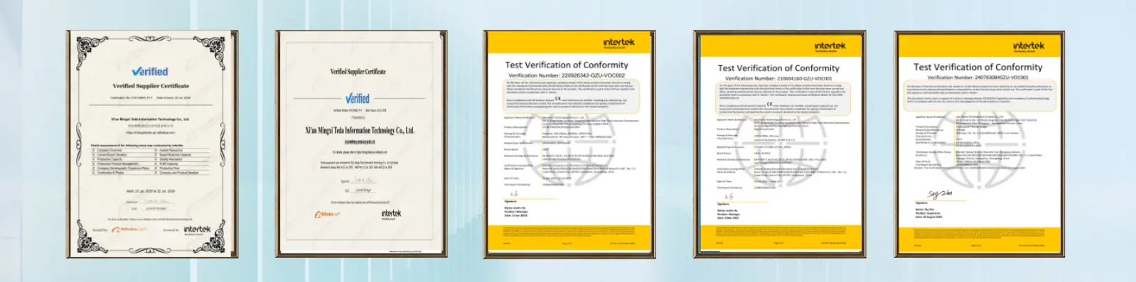

FAQs:
Q1: Why does testing an RCD (Residual Current Device) using the UT526 directly cause a complete power outage at the work site?
A1:
This is due to incorrect operating sequence or wiring. When testing the RCD's operating time or current, the instrument must be connected to the rear end of the RCD (load side). If connected incorrectly or other test keys are accidentally pressed during the test, the current will bypass the RCD and discharge directly to ground (equivalent to artificially creating a real grounding leakage fault), thereby triggering the tripping of the upstream protection switch.
Q2: Why does the instrument not respond or display zero when using Earth Continuity or testing current? What could be wrong with the motherboard?
A2:
-
The UT526's internal mainboard features a dedicated high-current overload protection circuit and a high-breaking-capacity fuse.
-
If the user accidentally connects a live high-voltage line while the circuit is in low-impedance mode, the protection diodes, current-limiting resistors, or fuses on the mainboard will be the first to trip and cut off the circuit. In this case, the casing needs to be opened to check whether the protection components and fuses at the mainboard input terminals have blown or burned out.
Q3: Why does the instrument's rotary band switch become obstructed, stuck, or unresponsive when switching bands?
A3:
-
As an industrial control device frequently used in harsh environments such as construction sites and power distribution rooms, dust and oil can easily enter the internal structure through the knob gaps.
-
Solution: Disassemble the casing and thoroughly clean the band switch PCB slide rails (usually circular gold-plated contacts) on the main board with anhydrous alcohol. Also check if the metal positioning springs on the back of the knob are deformed; adjust them and apply a suitable amount of conductive grease to restore crisp gear feedback and good electrical contact.

Contact Us
If you are looking for an affordable excellent choice. As the Resistance Tester product line, the UT526 Low Insulation Resistance Tester is highly competitive in the entry-level multi-functional electrical tester model resister tester market.It doesn't make you pay for features you don't need, yet it fully meets your requirements in terms of key measurement capabilities.
Email: manager03@mxtdinfo.com / manager02@mxtdinfo.com
Our customers’ satisfaction speaks for our quality — contact us to experience the same reliable service.
Our customers’ satisfaction speaks for our quality — contact us to experience the same reliable service.